

ComWinTop
Smoke sensor
Couldn't load pickup availability
Please notice: All prices are untaxed!
INSTALLATION AND MAINTENANCE INSTRUCTIONS
4-Wire Smoke Detector(Relay Output)
SPECIFICATIONS Operating Voltage Range: 9 to 28VDC Volts Non-polarized
Standby Current: ≤60µA @ 24 VDC
Maximum Alarm Current (LED on: ) ≤30mA @ 24 VDC
Operating Humidity Range: 10% to 93% Relative Humidity, Non-condensing
Operating Temperature Range: 14°F to 122°F (-10°C to50°C)
Adjustable Sensitivity: 1.06±.26%FT.
Height: 2.2˝ (55 mm) installed in Base
Diameter: 4.0˝ (103 mm)
Weight: 5.5 oz. (155 g)
INSTALLATION
BEFORE INSTALLING
NOTICE: This manual should be left with the owner/user of this equipment.
IMPORTANT: The detector must be tested and maintained regularly following NFPA 72 requirements. The detector should be cleaned at least once a year.
GENERAL DESCRIPTION
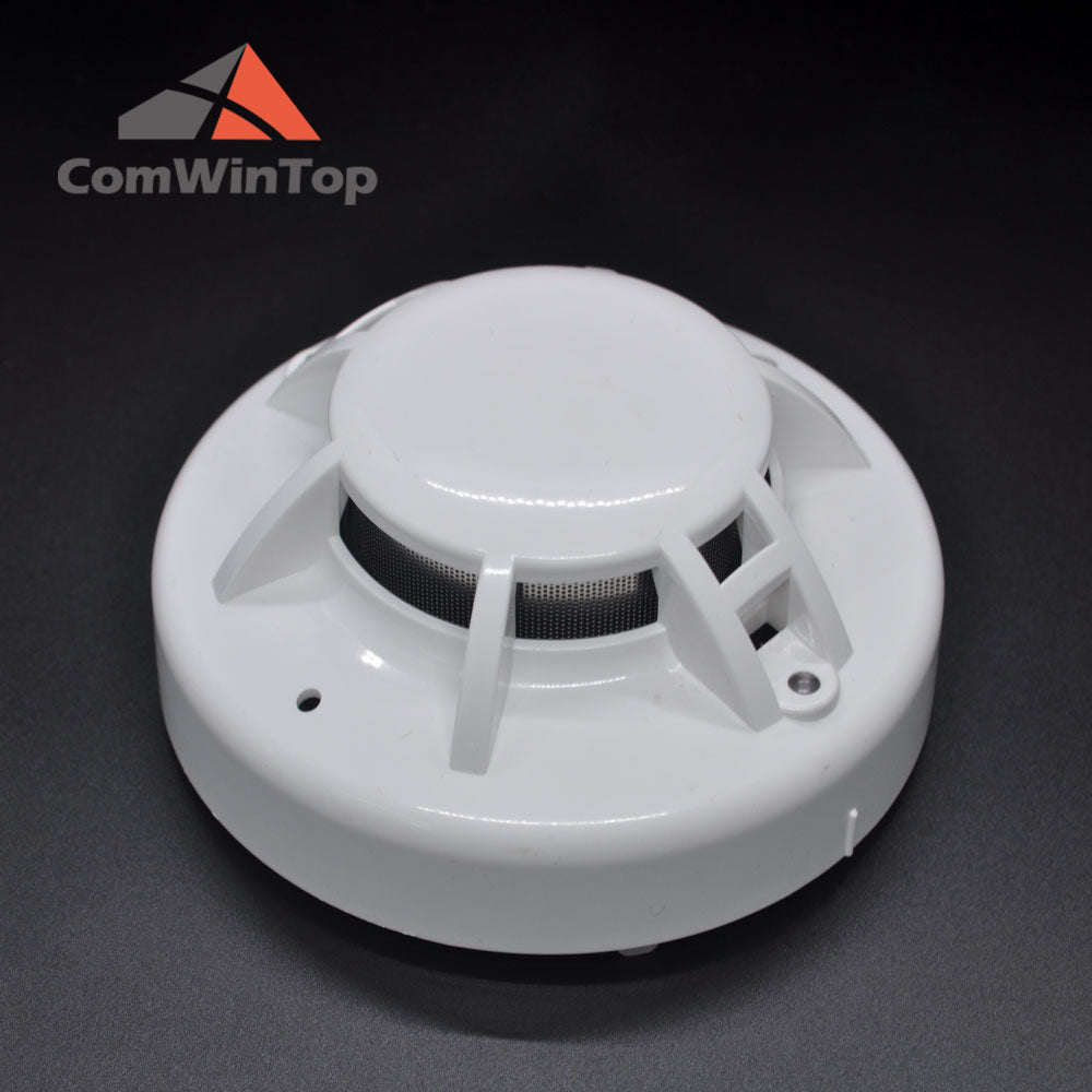
The device is photoelectronic detector uses a state of-the-art optical sensing chamber. This detector is designed to provide open area protection and to be used with most conventional fire alarm control panel.
Two LEDs on each detector provide local 360° visible alarm indication. They flash every 3~5 seconds indicating that power is applied and the detector is working properly.
The LEDs latch on in alarm. LEDs will be off when a trouble condition exists indicating that the detector sensitivity is outside the listed limit. The alarm can be reset only by a momentary power interruption.
INSTALLATION
NOTE: All wiring must conform to applicable local codes, ordinances, and regulations.
NOTE: Verify that all detector bases are installed, that the initiating-device circuits have been tested, and that the wiring is correct.
Remove power from initiating-device circuits before installing detectors.
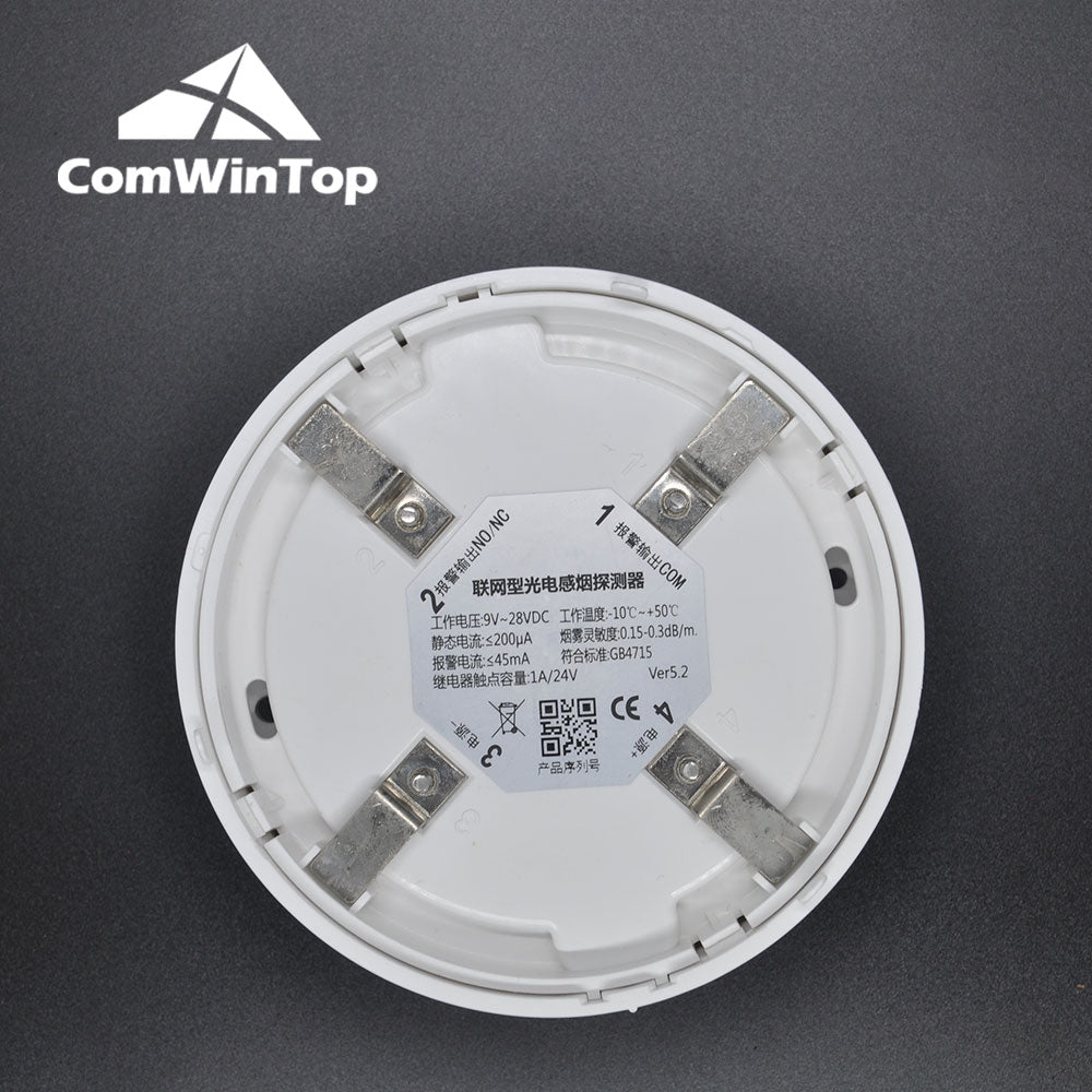
1. Wire the sensor base per the wiring diagram, Figure 1.
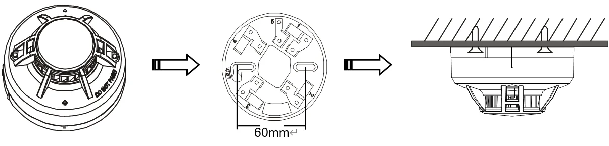
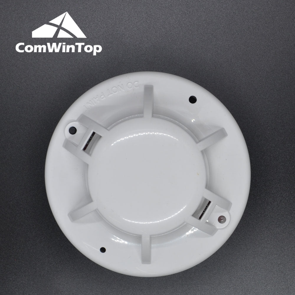
2. Install the sensor into the sensor base. Push the sensor into the base while turning it clockwise to secure it in place.
3. After all sensors have been installed, apply power to the control unit.
4. Test the sensor(s) as described in the TESTING section of this manual.
5. Notify the proper authorities that the system is in operation.

Figure 1. Wiring diagram

Introduce your content
Answer your customers' common questions
List a frequently asked question
Then provide an answer that will help your customer make an informed purchase.